 |
|
|
|
|
|
Have a Sales Question ??? Get Instant help online from our trained sales electronics specialists. |
|
|
|||||||||||||
![]()

| Table of
Content
Important Safety
Instructions Part II: Operating Your Receiver Everyday Operation Part
III: Installation & Programming Part
I: Getting Started For your protection, please read and observe all safety instructions before operating your satellite receiver. Keep these and any additional instructions for future reference. Installation
Ventilation: Slots and openings in the cabinet are provided for necessary ventilation. This unit should not be placed in a built-in bookcase, cabinet or other installation unless proper ventilation is provided. Allow 4-6 inches of open space on the sides and top of your receiver. Do not place the receiver on a bed, sofa, rug, or other similar surface that may block the openings at the bottom of the cabinet. Heat: Do not install the unit near heat sources such as radiators, stoves, heat registers, or other appliances that produce heat. Carts, Shelves, and Stands: Do not place this unit on an unstable cart, shelf, stand, tripod, bracket, or table. Care and Use Power-Cord Protection: Power-supply cords should be routed so that they are not likely to be walked on or pinched by items placed upon or against them. Pay particular attention to cords at plugs, convenience receptacles, and the point where they exit from the receiver. Power Plug: Any replacement plug must meet or exceed the manufacturer’s specifications. Power Source: Connect the unit to a power source only of the type described in the operating instructions or as marked on the appliance. Attachments: Do not use attachments not recommended by the manufacturer, as they may be hazardous. Grounding and Polarization: Do not defeat the grounding or polarization feature of the AC power cord. If you are unable to insert the plug into the outlet, contact an electrician to install a proper AC receptacle. AC Receptacle: Check to make sure that the AC receptacle holds the power cord plug securely. If the plug is loose, contact your electrician to replace the defective and unsafe AC receptacle. Overloading: Do not overload wall outlets and extension cords, as this may result in fire or electrical shock. Cleaning: Unplug the receiver from the wall
outlet before cleaning Do not use liquid or aerosol cleaners. Use a damp cloth for
cleaning. When Not In Use: Unplug the power cord if the unit is left unattended or unused for long periods of time or during lightning storms. (Disconnect the cord by grasping the plug. Never pull the plug out by the cord.) Unplug the receiver from the wall outlet and refer servicing to qualified service personnel when:
Replacement Parts: When replacement parts are required, be sure the service technician uses either replacement parts specified by the manufacturer or parts that have the same characteristics as the original components. Unauthorized substitutions may damage the unit or result in fire or electrical shock. Safety Check: After completing any service or
repairs to this unit, ask the service technician to perform safety checks to ensure that
it is in proper operating condition. Outdoor Antenna Grounding: If an outside antenna or cable system is connected to your
receiver, be sure the antenna or cable system is grounded to provide protection against
voltage surges and built-up static charges. Section 810 of the National Electrical Code
(ANSI/ NFPA No. 70-1984) provides specifications regarding proper grounding of the antenna
masts and support structures, grounding of the lead-in wire to the antenna discharge unit,
size of grounding conductors, location of antenna discharge unit, and connections and
requirements for the grounding electrode. The installer should refer to this NEC
specification to ensure proper antenna grounding. The following diagram shows a properly
grounded outdoor antenna system. Power Lines: The outside antenna system should not be located near overhead power lines or other electrical light or power circuits, or where it can fall onto power lines or circuits. When installing an outside antenna system, avoid touching power lines or circuits, as contact with them can be fatal. NOTE: Changes and modification not expressly
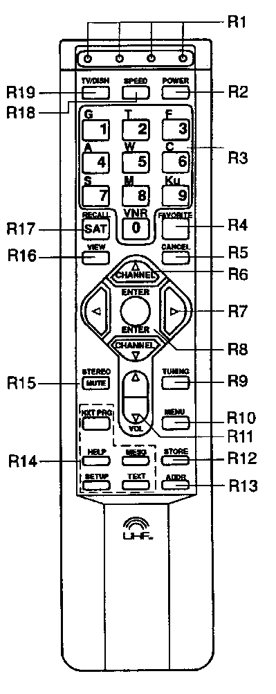
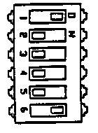
approved by Orbit Corporation could void the user’s authority to operate the unit. F1: Light Emitting Diode (LED) Display Panel When the receiver is in the normal viewing mode, this display shows the current satellite and channel or favorite program name. When the receiver’s power is off, the display will show the time if this option is selected in Custom Features. F2: [POWER]
F4: VideoCipher Signal Indicator F5: Stereo F6: MODE F7: [up/down]
|
||||
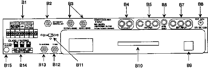
| B1: ACTUATOR TERMINAL
STRIP These terminals are used to attach the actuator motor and sensor wires. B2: Remote Control Antenna Connector B3: BLOCK DOWNCONVERTER IF INPUTS B4: VIDEOCIPHER ACCESSORIES B5: OUTPUTS B7: EXTERNAL INPUTS B8: EXTERNAL ACCESSORY B9: VIDEOpal PHONE CONNECTOR B10: UNIT ADDRESS NUMBER B11: CHANNEL 3/4 SWITCH B12: TV SET B13: TV ANTENNA B14: POLARITY SERVO TERMINALS B15: POWER CORD |
||||||||||||||||||||||||||||||||||||
|
||||||||||||||||||||||||||||||||||||
| INSTALLATION PROCEDURE STEP 1. Install the dish and mount according to the
manufacturer’s instructions. Using Line Amplifiers Depending on the type and length of coaxial cable being used, it may be necessary to use line amplifiers to compensate for signal loss. Line amplifiers are recommended when cable attenuation exceeds 25 dBs, and should be used only when necessary. (Line amplifiers use the same power as the LNBs, and no other connections are needed.) Determine the attenuation for the worst case using the following table, and select the appropriate cable.
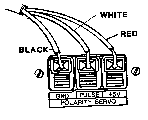
Signal Splitters STEP 6. Install the proper gauge of wire (following the instructions included with the feedhorn) between the feedhorn servo motors) and the Polarity Servo terminals on the rear of the receiver. The feedhorn has three wires, normally colored black, white, and red. Connect the black wire to the Polarity Servo "GND" quick connect terminal, the white wire to the "PULSE" terminal, and the red wire to the "+5V" terminal. If you are using an interconnecting cable with different colored wires, be sure the connections are correct. |
||||||||||||||||||||||||||||||||||||
|
||||||||||||||||||||||||||||||||||||
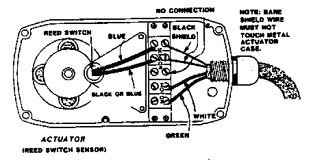
| STEP 7.
Install the actuator cable between the actuator and the Motor/Sensor terminal strip on the
back of the receiver. Connect the wires to the actuator, following the manufacturer’s
instructions. The other end of the actuator cable should be connected to the terminal
strip on the back panel of the receiver as follows: a.
Connect the white and green wires to the MOTOR terminals labeled WHT/GRN and GRN/WHT. If
these wires are connected in reverse order from their connection at the actuator, the dish
will move east when it should move west, and vice versa. |
||||||||||||||||||||||||||||||||||||
|
||||||||||||||||||||||||||||||||||||
|
||||||||||||||||||||||||||||||||||||
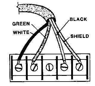
| Note: Be certain to select
at least 14 gauge motor wire, and 20 gauge sensor wire when connecting the actuator cable.
The 14 gauge motor wire will allow cable runs of up to 500 feet with an acme actuator
jack, or 1000 feet with a ball-screw actuator jack. Smaller motor wires are not
recommended. The 20 gauge sensor wire must be shielded; connect the shield wire at both
the actuator and the receiver. A special 5-conductor actuator cable (suitable for normal
installations) is available through most dealers. STEP 8. If you are using a local (rooftop) television antenna, connect the coaxial cable to the TV ANTENNA connector on the back of the receiver (labeled B13 on the Back Panel figure). The television will receive signals from the local antenna whenever the satellite receiver is turned off. STEP 9. Install a coaxial cable from the television to the TV SET connector on the back of the receiver (labeled B13 on the Back Panel figure). If you are using a video monitor or VCR, use the OUTPUT connectors labeled "LEFT-RIGHT-VIDEO" on the back of the receiver (labeled B5 on the Back Panel figure). STEP 10. Set the rear panel modulator switch labeled CH 3/4, to the desired TV channel. Use the channel that minimizes interference from local stations transmitting on either channel three or four. STEP 11. Set the dish on a polar arc. To aid in setting the dish on the polar arc and properly aligning the feedhorn on the polar axis, you may use the receiver to change channels and move the dish. If problems are encountered with the dish or feed system, please correct them before continuing. Use the CHANNEL [<] [>] buttons on the remote control to change channels. Use the TUNING [i] button on the remote control to move the dish to the west, and the TUMNG [i] button to move the dish to the east. If the dish moves in the wrong direction, unplug the receiver from the wall outlet and reverse the white and green wires on the MOTOR terminal strip located on the receiver’s back panel (refer to Step 7(a). |
||||||||||||||||||||||||||||||||||||
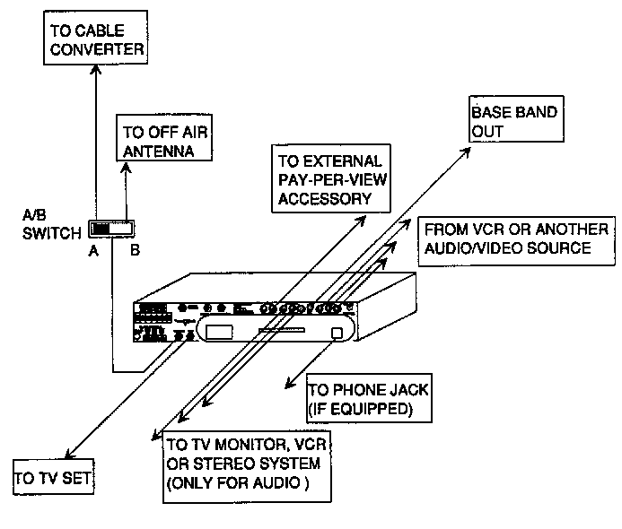
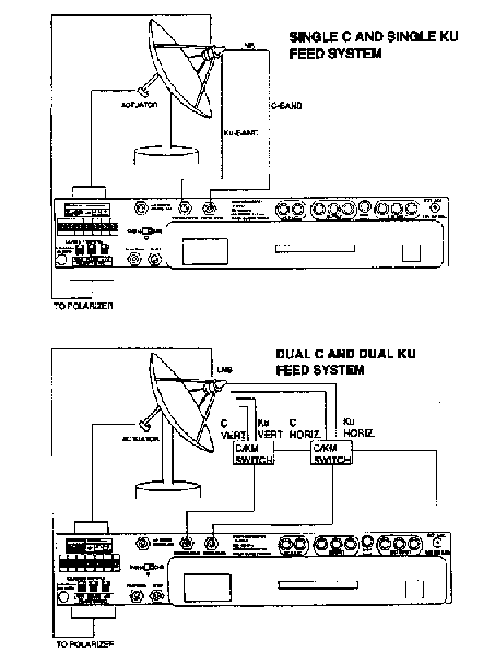
| SYSTEM CONFIGURATIONS The two illustrations below show different configurations and back panel connections for your receiver. |
||||||||||||||||||||||||||||||||||||
|
||||||||||||||||||||||||||||||||||||
| PROGRAMMING
CAUTION: Prior to setting the east and west limits, care must be taken to ensure that the actuator is not allowed to extend or retract to a point where it can lose leverage or run the dish into the ground or nearby objects. The actuator should not be allowed to extend or retract beyond the point where the internal slip clutch engages. When this occurs the actuator will make a loud popping noise and an on-screen "MOTOR ERROR" message will be displayed. If you have not already done so, refer to the instructions included with the actuator for information on how to properly and safely install the actuator. Programming should begin only after the antenna has been accurately set on a polar arc and the correct east-west dish movement has been verified. The EchoStar 710 is pre-programmed with the formats of all commercial satellites broadcasting to North America, as well as the polarity, and audio and video frequencies for the active channels on each of them. These formats will automatically be recalled as each satellite is programmed. Programming the EchoStar 710 consists of setting limits and programming satellites. Satellite programming is accomplished manually by locating each satellite. Setting Limits: To set the east limit: After setting the east limit, the installer can begin programming satellites with the aid of AutoPrompt. AutoPrompt is described on the following page. To manually program satellites, you must now set the west limit. To set the west limit: Once both limits have been set you can move the dish to any position within them. If you move the dish to one of the limits, the dish movement will stop and inform you that you cannot move past the stored limit. If it ever becomes necessary to reset the limits, refer to "Custom Features: Installation Options". You can now manually program satellites or use AutoPrompt. |
||||||||||||||||||||||||||||||||||||
| PROGRAMMING SATELLITES
Your receiver’s AutoPrompt feature allows you to program the entire satellite arc with minimum manual interaction. After storing the east limit, press [ENTER] to begin AutoPrompt or [CANCEL] to exit. If you decide to start AutoPrompt at another time, such as after storing the west limit, press [4][3]. You must be in Dish Tuning in order to use AutoPrompt. If you want to skip a satellite during AutoPrompt, refer to item number 9 on the following page. The following example discusses programming C-band satellites from east to west after setting the east limit and programming Ku-band satellites from west to east.
1. Press Enter
2. Press 1 to select the direction for programming the
satellite arc (EwW, EwW). 3. Press 2 to select C-band satellites, Ku-band satellites or
both. For systems that are setup for both C and Ku, we recommend selecting C-band only for
programming from east to west. Since Ku satellites are harder to locate, it is easier to
first find the C-band satellites and use these as references to locate Ku-band satellites.
4. Press 3 to begin programming. You may wish to use Channel Scan to assist you in
locating satellites. Press [6][7] to turn Channel Scan on or off. |
||||||||||||||||||||||||||||||||||||
|
5. Press the appropriate tuning key [i]
or [i] to move the dish to the proper satellite. Refer to the Satellite Reference Chart on
the following page. 6. Scan through a few channels to verify that the satellite you are at is the satellite that AutoPrompt is requesting. 7. Press [STORE] to save this satellite. VNR is automatically turned on when you press [STORE]. If you wish to disable VNR for the satellite you are on, press [6][5]. 8. AutoPrompt will now bring up the next satellite to be programmed. Once again, use the proper tuning key to move the dish to locate the satellite. Press [STORE]. |
|||||||||||||||||||||||||||||||||||
| 9. If you would like to skip a satellite, press [SAT]. | ||||||||||||||||||||||||||||||||||||
|
10. Use the tuning keys to scroll past the satellite you wish to skip and press [ENTER]. You only need to use this step to skip a satellite. 11. When you have programmed the western most satellite, press [CANCEL] to exit AutoPrompt. 12. Move the dish to the west limit and press [STORE]. 13. If you have a C/Ku setup, start AutoPrompt again to program your Ku satellites (Dish Tuning). 14. Press [4][3] and enter the Installation password. |
|||||||||||||||||||||||||||||||||||
15. Select the EwW direction, and "All" for "Band Select." 16. Press 3 to begin programming. 17. AutoPrompt will now bring up the nearest satellite. If the satellite has not been programmed yet, it will ask you to move to the satellite. If the satellite has been programmed, press [ENTER) to move to it. HINT: Go to C-barid satellites that are dose to Ku-band satellites. This will assist you in locating Ku-band satellites. NOTE: During high wind conditions, the automatic dish peaking may not accurately peak on Ku-band satellites. |
||||||||||||||||||||||||||||||||||||
Manually Programming Satellites When programming satellites, it is necessary to name the satellite to be programmed, prior to locating it. Your receiver is pre-programmed with the formats of all available commercial satellites, as well as the polarity, and audio and video frequencies for the active channels on each of them. These default parameters will be recalled for each satellite when that satellite’s name is keyed-in during programming. Once the receiver knows which satellite you’ll be looking for, you should be able to see and hear the default channel when you aim the dish in the right direction. The default channel number will flash briefly on the screen when you name the satellite. It is essential that the satellite being viewed is, in fact, the satellite that has been requested. For this reason it is always a good idea to refer to a current satellite TV programming guide to correctly identify the satellite. The table on this page lists the satellites whose formats and default channels are pre-programmed into the receiver. This table lists the name and number designation that should be entered prior to programming each satellite. (Satellite television programming guides will also list these name and number designations.) Although your receiver provides a number of pre-programmed satellites, you will not necessarily be able to receive broadcasts from all of them. Satellite television reception depends not only on the broadcasters, but on the size of your antenna and your geographical location as well. It is important to make sure you are within a particular satellite’s "footprint," or viewing area, prior to trying to locate it. Due to changes in satellite positions and names, this chart is subject to change. Refer to a current satellite reference chart at the time of installation for the latest information. |
||||||||||||||||||||||||||||||||||||
|
||||||||||||||||||||||||||||||||||||
| Satellites to become active in the near future. | ||||||||||||||||||||||||||||||||||||
| PRE-PROGRAMMED
SATELLITES FOR FUTURE LAUNCHES: Telstar T###
Format: T4, T5 |
||||||||||||||||||||||||||||||||||||
|
||||||||||||||||||||||||||||||||||||
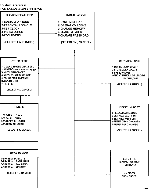
| Custom
Features: INSTALLATION OPTIONS There are a number of installation options that may be selected through the use of Custom Features. These options are accessed by selecting the "Installation" option from the Custom Features main menu. Press [MENU] to display this menu. The first time the Installation option is selected, the on-screen menu will request you to set an Installation password. Most viewers will find it advantageous to password-protect the Installation Custom Features, since a number of them can adversely affect the system’s performance if they are accidentally programmed. If you wish to password-protect the Installation Custom Feature, follow the on-screen instructions. It is a good idea to use a number that you will easily remember for the password. Note: The Custom Features Installation Password is not the same as either the Parental Lockout Password or the VideoCipher ’Rating Ceiling Password." Once a password has been entered, the Installation main menu will be displayed. From this menu you may select one of five different options. Selecting an option will access another set of special menus that will allow you to make the 1nstallation changes. For your convenience, a flowchart is provided on the next page that shows how each INSTALLATION option may be accessed from the various menu displays. The following pages describe the use and operation of each installation option. |
||||||||||||||||||||||||||||||||||||
SYSTEM SETUP The SYSTEM SETUP option allows you to customize your receiver to match the system configuration, as well as select important tuning options. Some of these selections will toggle (switch) the option’s setting, but others will present additional displays, or require special tuning operations. 1 and 2. Feedhorn Options: For the proper back panel connections in a dual feed system, refer to the configuration diagrams in this section. 3 and 4. Automatic Dish and Polarity Peaking: Once an automatic peaking routine is toggled to the off position, you will either be able to manually re- peak the dish position or polarity angle, depending on which tuning mode the receiver is in. These manual adjustments will not affect dish positioning for satellites other than the current one, or the polarization angle of oppositely polarized channels. To manually re-peak dish position: To manually adjust the polarity angle: |
||||||||||||||||||||||||||||||||||||
5. Polarizer Power Option This option toggles between continuous (on) and pulsed (timed) power to the polarizer or polarization accessory. There is a three second delay in switching the power on and off. Under normal operating conditions, the option should be pulsed. The continuous option should be used for polarizers that require continuous power or in extremely cold areas where the polarizer could freeze if it is not continuously moved. 6. Adjust DRO This option can be set independently for C-Band and Ku-Band LNBs by selecting either a C-Band or Ku- Band satellite prior to selecting the Adjust DRO option. To adjust the DRO frequency: 7. Filters 1 through 4. VNR and TI ON or OFF All Channels |
||||||||||||||||||||||||||||||||||||
| OPERATION
LOCKS This Installation option allows you to enable or disable the receiver’s ability to change or store fine tuning parameters and customized settings. In addition, the Operation Locks menu provides the SHORT/LONG List Length selection for the Front Panel Mode. 1 and 2. TUNING and STORE Locks If STORE LOCK is toggled on, the [STORE] button will not change the receiver’s programmed information. 3. SPEED STORE Normally you will need to press [STORE] to program tuning changes and special options in the receiver’s memory. If you do not press [STORE] all of the changes you have made (regardless of the channel) will be lost when you select a different satellite. This is desirable if you only want to make "temporary" fine tuning adjustments. If you want to make your adjustments and selections permanent, press [STORE] after making all of the desired changes for the current satellite. If you are making a number of tuning adjustments (perhaps during the initial installation of your system) you may wish to bypass the need to press [STORE] for every set of satellite changes. If you wish to make your tuning changes and selections permanent as you perform the adjustments, toggle the Speed Store option on. Normally Speed Store should be off to prevent accidental changes from automatically being saved in the receiver’s memory. To toggle Speed Store on and off, key-in [MENU] [4] and then enter the Installation password. (If an Installation password has not been set, press [ENTER].) Press [2] to select the "Operation Locks" options and then [3] to toggle "Speed Store" on or off. 4. Front Panel List Length The CHANGE MEMORY option allows you to change the receiver’s memory in a number of different ways. There are seven selections available from the CHANGE MEMORY main menu. Some of the selections switch the option’s setting, and others access additional menus or require special adjustments. 1. RE-SYNC ACTUATOR This option is useful when repairing or replacing the actuator or defective sensor wires; reconnecting loose actuator wires or clamps; or correcting any other problem that has caused the dish position to be displaced the same amount on every satellite. The RE-SYNC ACTUATOR option allows you to align the actuator to match the receiver’s currently stored satellite positions, preventing you from having to re-program the receiver. To re-sync the actuator: 1. Select a known active satellite and channel using the [SAT] button and the alphanumeric keypad. If the actuator is not in sync, you will probably not see a picture on the TV screen. 2. Enter the Custom Features Installation mode and select the CHANGE MEMORY option. Key-in the number for RESYNC ACTUATOR. (The receiver will automatically select Dish Tuning.) 3. Use the [<][i] keys to move the dish to the satellite you selected in the first step. The on-screen display will show the current dish count. 4. Once you have correctly identified the satellite, press [STORE]. If AUTO DISH ON/OFF has not been toggled off, the receiver will optimize the dish position and polarity angle for the current satellite and channel. After a single satellite has been relocated, your receiver will be able to accurately locate all of the other previously programmed satellites. 5. After the receiver re-syncs the actuator, select several satellites and verify their identity to be sure that the actuator problem has been corrected. 2 and 3. SET NEW EAST/WEST LIMIT 1. While the receiver is in the Installation Custom Features Mode, select the CHANGE MEMORY option, and key-in the number for setting either a new east or west limit. (The receiver will automatically select Dish Tuning.) 2. Use the [<] [>] buttons to move the dish to the new limit. 3. Press [STORE]. Use the [CANCEL] button to exit from Custom Features and Dish Tuning. Note that the limits can only be extended by 200 motor counts at a time. This is to prevent the user from over- extending the actuator arm. 4 and 5. RESET CHANNEL and SATELLITE CHANGES |
||||||||||||||||||||||||||||||||||||
ERASE MEMORY
1. ERASE A SATELLITE 2. ERASE ALL SATELLITES 3. ERASE ALL FAVORITE PROGRAMS 4. ERASE ALL MEMORY If ERASE ALL MEMORY is selected and confirmed, your unit will operate exactly as it did when you first took it out of the box. The receiver will be reset and the on-screen menu will prompt the user to set an east limit. The factory pre-set information will not be erased, and will be recalled as each satellite is re- programmed. This option should be used when the unit is being programmed after servicing, or installation at a new location. If you ever need to change your installation password, use this option to do so, following the instructions provided by the on-screen menu. IF YOU FORGET YOUR PASSWORD
XPERT REMOTE CONTROL ADDRESSABILITY NOTE: The following instructions for the XPERT
Remote should only be used if you are experiencing UHF interference in your area. Addressability is one of the newest features to the HTS XPERT Remote Control. It programs the satellite receiver to block out incoming signals from other UHF remotes in your home or neighborhood. This is very useful if you have UHF interference in your area. Inside the battery compartment of the remote, you will notice a
dip switch like the one pictured at right. Should you experience a problem with the
operation of the remote, please ensure the switch settings match this diagram. Also,
before addressing, the dip switch must be set as shown (right). CAUTION: When changing batteries, DO NOT press any remote keys. Note: Previously programmed SPEED keys will need to be reprogrammed.
To activate another address: (The XPERT remote is shipped from the Dip Switch Setting factory on ADDRESS "0".)
To verify the address number currently being transmitted by the remote, depress the [ADDR] key twice. The current address number will be displayed by one of the 4 LEDs on the remote. The LEDs are numbered 0 to 3 from left to right. If more than 4 address numbers are desired, please consult your satellite dealer. CAUTION: Do not use a sharp object to press the [ADDR] button on the remote. We recommend using a car key, fingernail, paper clip, or other blunt-tipped instrument. NOTE: In rare circumstances, brief interruptions of UHF transmission may occur. This happens when two UHF remotes are transmitting at exactly the same time. Wait a few seconds and normal operation will resume. |
||||||||||||||||||||||||||||||||||||
| RESETTING THE XPERT REMOTE You may need to dear the memory of the XPERT remote to regain normal operation, when batteries are installed, a dip switch setting is changed, or you are experiencing a inoperative remote.
If you have an XPERT with dip switches: (shown on previous page)
If you have an XPERT with NO dip switches:
If you had previously changed the Addressability feature on the XPERT remote, you will need to perform the following to reset the unit and the remote to ADDRESS 0:
COMPATIBILITY WITH THE STANDARD ECHOSTAR UHF REMOTES The EchoStar 710 and the XPERT~ Remote incorporate a new 10-bit addressable UHF technology for the transmission of keycodes. It is possible to use a standard EchoStar "5-bit" remote on the 710. If you wish to operate your receiver with this remote, follow the procedure below:
NOTE: To resume use of the XPERT remote, follow the above procedure pressing the POWER button on XPERT remote instead
|
||||||||||||||||||||||||||||||||||||
| TROUBLE SHOOTING PROBLEM: Unit does not respond and VideoCipher indicator light is flashing slowly. Unit does not respond and VideoCipher indicator light is flashing slowly. CAUSE/SOLUTION: PROBLEM: CAUSE/ SOLUTION: PROBLEM: No picture or sound, but indicator lights are lit. CAUSE/ SOLUTION: PROBLEM: Picture has sparkles or picture is grainy. CAUSE/SOLUTION: PROBLEM: CAUSE/SOLUTION: PROBLEM: CAUSE/SOLUTION: CAUSE/SOLUTION: Selected AUDIO is not tuned to proper subcarrier. Select another AUDIO or tune the selected subcarrier for clear reception. Satellite is transmitting poor audio. Tune to another channel. Try a different audio bandwidth filter, PROBLEM: Remote control does not operate or has poor range. CAUSE/SOLUTION: Weak battery in remote. Replace battery. UHF remote antenna is not positioned properly. Move antenna slightly. NOTE: Obstructions such as walls, refrigerators, PROBLEM: CAUSE/SOLUTION: Loose actuator mounting on dish. Tighten bolts. Loose bolts on dish. Tighten bolts. Loose or defective pivot bearing on dish. Tighten or replace bearing. Defective sensor. Replace or rotate sensor. Installation done without shielded wire. Replace sensor wire. Realign all satellites in the controller memory. Refer to INSTALLATION in the Custom Features section of this manual and use the Re-Sync Actuator Option. Use caution when realigning dish to insure that the actuator does not over-extend. PROBLEM: Dish does not return accurately to ONE satellite. CAUSE/SOLUTION: Reprogram the problem satellite. Enter DISH Tuning and press [5][5] to peak the signal. Press [STORE]. Service information can be obtained by either calling Orbit Communication Service at 978-440-8899 |
||||||||||||||||||||||||||||||||||||
NOTE: To receive the benefits of this ninety day limited warranty, you must sign Orbit's invoice and return the enclosed envelope within 10 days of purchase. Be sure to retain a dated Proof of Purchase! Your EchoStar IRD is manufactured to Orbit’s Corporation’s specifications. The receiver warranty is limited to parts and labor for a period of neonate day. Orbit feeds are also covered for ninty day. Orbit LNBs and actuators are covered by a two year warranty. To receive the benefits of your warranty, you must be accompanied and return the enclosed warranty registration card within 15 days of the purchase date. The warranty extends only to the original purchaser of the equipment and is limited to the purchase price of each component. All claims under this warranty must be accompanied by proof of purchase. This warranty does not cover damage due to lightning (except for LNBs), power line surges, fire, flood or other acts of God, improper use, repair, or alteration by other than Orbit Corporation or one of its authorized repair centers, abuse, negligence, or improper installation or operation. This warranty does not cover any damage to actuators due to bent tubes or adverse weather conditions. In no event shall the manufacturer be held liable for any incidental or consequential damage resulting from the use of the equipment. The manufacturer reserves the right to refuse to extend this warranty if any of the above exceptions are determined to have caused the equipment not to have performed properly. Replacement parts supplied under this warranty are warranted for the remaining portion of the original warranty period. Equipment must be properly packaged and returned to Orbit Corporation, 90 Inverness Cirde East, Englewood, Colorado 80112, or to one of its authorized service centers. Prior to returning any equipment to Orbit Corporation, the purchaser must obtain a "return authorization number" from the Orbit service center. Cost of removal, transportation to the service center, and reinstallation will be paid by the purchaser. An evaluation fee, plus shipping charges, may be assessed the purchaser by Orbit Corporation if the returned merchandise is deemed by Orbit to be operating properly. This warranty gives you specific legal rights which may vary from state to state. Some states do not allow the exclusion or limitations of incidental or consequential damages, or allow limitations on the duration of an implied warranty, so the above limitations may not apply to you. Service information can be obtained by either calling your Orbit Communication 978-440-8899. If you ever forget your Parental Lockout or Installation password, you’ll not be able to regain access to these important features. For this reason your receiver has a "master password" which will set both the Parental Lockout and Installation passwords to "[ENTER]." Once the passwords have been reset, you can access each feature by pressing the [ENTER] button when the receiver requests the password. You may wish to set new passwords, once you regain access to each feature. To use the Parental Lockout and Installation "Master Password":
You may want to write this number and store it in a safe place to avoid loss of your Custom Feature passwords. |
||||||||||||||||||||||||||||||||||||
![]()